The video below shows my Homebrew SDR rx working with the GUI on the STM32F746-Discovery board.
However, what you might notice is the presence of image products in the waterfall. The processing of the signal suppresses all but the very strongest of these so they don't appear as audio but it is mighty confusing when they are on the waterfall but actually not there (if you see what I mean)! I am in the process of building a QSD or Tayloe Detector, which should provide better rejection of images. I have breadboarded one of these, it works but not very well. I think that this might be due to the length of leads I have on the breadboard so I am trying to use Eagle CAD to design a circuit board to overcome these problems.
It's been a little while since my last post but I have been wrestling with software. To summarise, my software stack is:
FreeRTOS - a real time operating system for microcontrollers that enables an easy way to prioritise tasks without having to resort to 'bare metal' handling of interrupts. FreeRTOS is free with no licence issues.
uGFX - initially I was planning to use STemWin as a graphics manager but, although free to use it is closed source. As I couldn't get it to work with FreeRTOS I decided to use an open source graphics manager and found uGFX. This decision has not been without its problems but after I found the bug in the uGFX code I was able to work around it.
DSP Concepts Audio Weaver - this software is closed source but licenced by ST for use on their microcontrollers. However, as it is fantastic it is worthwhile persevering with. You do have to register to download it but no payment is required.
So, to cut a very long story short I now have FreeRTOS, uGFX and Audio Weaver running together. I have taken NT7S's Si5351 library code that G7UVW had ported to the mbed platform and in turn I have ported it to C to work with the ST hardware abstraction layer.
I can now tune the Si5351 from the STM32F746-Discovery board using the touch screen while the DSP processing provided by the Audio Weaver library is also running. The one niggle that I have yet to resolve is that when I disconnect & reconnect power from the microcontroller the audio processing doesn't work on reboot although the rest of the program (graphics etc.) does.
For now though I'll focus on the design of the signal processing in Audio Weaver.
Audio Weaver Designer runs on Windows (I've tried it on Linux with Wine but with no success) and is used to design and build the audio processing by joining blocks together. Even better is that it is possible to deploy the process you have designed onto the microcontroller and run it while allowing you to change settings in Windows. This approach leads to a quick development time and tuning is easy. When the design is completed it is a simple operation to create the files required to incorporate them in the microcontroller code.
There is an argument that this approach is the easy one but I liken it to the discussion around using an LM386 or NE602 when discrete components could be used. It's a tool and it works so I'll use it.
The image below shows Audio Weaver Designer:
The available modules are selected from the folders on the left and dragged into the process and the connectors are then joined together and any parameters added/changed.
The images below shows annotations against each major functional block of my DSP processing:
This method of SSB demodulation is not the Weaver (or third) method as I have read elsewhere but a bit of a hybrid. I will be trying other configuration to assess which is best for my application. A good description of the different methods of SSB demodulation is here.
While testing this process through Audio Weaver Designer I am controlling the Si5351 tuning via an Arduino Uno using the sketch I put in a previous post. The Audio Weaver file in the pictures is available for download here if you want to try it yourself.
A video of reception using this process flow while it is running on the Windows machine connected to the microcontroller is below.
Next post: Bringing it all together on the STM32F746-Discovery board.
I recorded this video of the I/Q outputs fed into my computer with the demodulation being performed by sdr# (now with audio)
The large central spike is, I think, bleed through from the local oscillator signal. My next task is to measure the loss in the receiver and also look at whether there is a ground loop problem. Next post: Introduction to the microcontroller processing.
We are now at the point where we need to take the signal from the Si5351, divide it by 4 and produce two outputs, one of which is 90 degrees out of phase from the other. A good tutorial on this process is here although we will divide by 4 rather than 2. The datasheet for the 74HC74 is here. The 74AC74 and 74HC74 are more or less interchangeable, the difference being that one can handle higher frequencies than the other. There are many circuits on the Internet for quadrature dividers but I used one that is used in the SoftRock Ensemble receiver, here. The only difference being that the outputs to QSD CLK0 & CLK1 are not used, however, note that pin 9 does need to be connected to pin 2 (it took me a while to figure that was the reason I couldn't get it to work). Pin 14 is fed with 5V from the 7805 regulator and pin 3 is fed from CLK0 output on the Si5351. The outputs from pin 5 and 8 are individually fed to the LO ports on ADE-1 #1 and ADE-1 #2. Below is my version, it looks a bit messy but it works.
The screenshot from my oscilloscope shows the two out of phase outputs from the quadrature divider in yellow and blue. The purple line shows the that these two outputs have been divided by 4 and are at a frequency of 7.100 MHz.
We are now ready to see what this thing can receive by taking the I & Q outputs from the audio LPF's to a stereo jack plug (I to left channel, Q to right channel or vice versa plus ground) and plugging it into our computer to listen to the signals using SDR# but finally a picture of the completed RF splitter, mixer, AF low pass filter, regulator, quadrature divider board.
I was going to mount the Si5351 breakout board onto the two posts top right but I think the board uses imperial screw size holes as my M3 screws will not quite fit. Next post: Connecting to SDR#
The Si5351 is "...an I2C configurable clock generator that is ideally suited for replacing
crystals, crystal oscillators, VCXOs..." That is to say that it can generate frequencies from 2.5 kHz up to 200 MHz. Adafruit Industries produce a breakout board with the Si5351 chip and other required components installed for under $8, this allows us to interface with a microcontroller, e.g. Arduino, and control the frequencies produced very easily. The breakout board allows us to generate three frequencies but for this project we will only be using one of the outputs. We will produce a frequency that is four times the LO frequency we require, when the signal goes through the quadrature divider (74AC74 flip-flop) it will be divided by four to produce the LO frequency. Adafruit Si5351 breakout board on the left, Arduino Uno on the right.
The connections are simple: +5V and GND from the 7805 regulator, pin A4 from the Arduino Uno connected to pin SDA on the breakout board and pin A5 connected to pin SCL. I have hacked the example program below, it sets the Si5351 to a default frequency of 28.4 MHz, i.e. 7.1 MHz after the divide by 4, and by using the serial monitor window in the Arduino IDE you can change frequency in 1 kHz steps up (1) or down (2), or 100 Hz steps up (+) or down (-). This frequency is output on CLK0 - the next step is to connect CLK0 to the 74AC74 flip flop. You will need to install the Si5351 library by following the instructions here.
/* * si5351example.ino - Simple example of using Si5351Arduino library * * Copyright (C) 2015 Jason Milldrum <milldrum@gmail.com> * * This program is free software: you can redistribute it and/or modify * it under the terms of the GNU General Public License as published by * the Free Software Foundation, either version 3 of the License, or * (at your option) any later version. * * This program is distributed in the hope that it will be useful, * but WITHOUT ANY WARRANTY; without even the implied warranty of * MERCHANTABILITY or FITNESS FOR A PARTICULAR PURPOSE. See the * GNU General Public License for more details. * * You should have received a copy of the GNU General Public License * along with this program. If not, see <http://www.gnu.org/licenses/>. */
#include "si5351.h" #include "Wire.h" Si5351 si5351; char incoming_char; long serial_input_number, serial_input_number1; void setup() { // Start serial and initialize the Si5351 Serial.begin(57600); si5351.init(SI5351_CRYSTAL_LOAD_8PF, 0); // Set CLK0 to output 7.1 MHz with a fixed PLL frequency si5351.set_pll(SI5351_PLL_FIXED, SI5351_PLLA); si5351.set_freq(2840000000ULL, SI5351_PLL_FIXED, SI5351_CLK0); serial_input_number1 = 7100000; } void loop() { if(Serial.available()>0){ incoming_char = Serial.read(); switch(incoming_char){ case '1': //up by 1kHz serial_input_number1 = serial_input_number1 + 1000; serial_input_number = serial_input_number1 * 4; si5351.set_freq((serial_input_number) * 100ULL, SI5351_PLL_FIXED, SI5351_CLK0); Serial.println(serial_input_number1); break; case '2': //down by 1kHz serial_input_number1 = serial_input_number1 - 1000; serial_input_number = serial_input_number1 * 4; si5351.set_freq((serial_input_number) * 100ULL, SI5351_PLL_FIXED, SI5351_CLK0); Serial.println(serial_input_number1); break; case '+': //up by 100Hz serial_input_number1 = serial_input_number1 + 100; serial_input_number = serial_input_number1 * 4; si5351.set_freq((serial_input_number) * 100ULL, SI5351_PLL_FIXED, SI5351_CLK0); Serial.println(serial_input_number1); break; case '-': //down by 100Hz serial_input_number1 = serial_input_number1 - 100; serial_input_number = serial_input_number1 * 4; si5351.set_freq((serial_input_number) * 100ULL, SI5351_PLL_FIXED, SI5351_CLK0); Serial.println(serial_input_number1); break; } Serial.flush(); } }
A 7805 regulator circuit used to convert ~12V to 5V is here. When you run the Arduino sketch you should be able to hear the output from the Si5351 on an HF receiver at 28.4 MHz Next post: Quadrature Divider
The ADE-1 is a passive device with an RF and LO input and an IF output. Two ADE-1's are used with the RF port on each being fed with output from port 1 and 2 of the RF splitter respectively (Note: I changed the design of the RF splitter from that which I first published, here is a link to the updated page). The LO ports will be fed from one of the two outputs of the 74AC74 flip-flop respectively. The output of the IF ports goes to an audio frequency LPF (one LPF per port). The theory behind how the I & Q signals are produced are described in this excellent YouTube video by Craig, devttyS0. In short the LO outputs are produced by dividing the signal from the Si5351 by 4, there are two outputs from the 74AC74 at the LO frequency and one is 90 degrees out of phase from the other. When each one of these is mixed with the RF in the ADE-1 we end up with two outputs at baseband audio frequency, I & Q, one being 90 degrees out of phase from the other as shown below:
The audio LPF that follows each RF output I copied from EA4NZ
Source: EA4NZ
Below you can see a picture of the RF splitter, ADE-1's and audio LPF's. The 7805 and assorted capacitors in the top right is the 5V supply for the 74AC74.
I note from devttyS0's video that the FST3253 device removes the need for the two ADE-1's by implementing a Tayloe Detector - something to be tried.
The RF splitter is used to split the incoming RF into two equal parts. These individual signals are then used as input to the ADE-1 mixers that produce the I & Q signals (90 degrees out of phase). Obviously you don't want to lose too much power in the splitter circuit and you want to ensure that the two output signals are of equal magnitude. Update: 27 Dec 2017. The splitter design I originally used did not produce zero phase difference. Hence I have updated this page with another design. I built this splitter based on a design from EMRFD (Experimental Methods in RF Design, Hayward, Campbell & Larkin), specifically the one from the 18 MHz transceiver shown in Fig. 11.14. The schematic is below:
I used an FT50-43 toroid with 6 bifilar turns. My built version can be seen in the picture below.
The picture below shows the outputs from ports 1 and 2. They are equal in amplitude and in phase which is perfect.
The band pass filter (BPF) is used to filter out strong signals from outside of the frequency band of interest. I have built a 7MHz BPF so the receiver will initially be limited to the 40m band. However, to cover other bands a BPF will be required per band and switched in and out of circuit as the receiver is tuned to the different bands. I used a circuit that I found on VK4FFAB's site, I initially built this as input to a NE602 mixer where the impedance needs to be 1500 ohms but for this project replaced the 270 & 18 pF capacitors with 220 & 56 pF ones to create 50 ohm output. The circuit schematic is below, the output is chopped off but is just to the right of the 18pF capacitor with the output of the 18pF capacitor carrying the signal to the next stage.
Having built the circuit I connected my Wideband RF Noise Generator to the input of the RF amp and the output of the RF amp to the input of the BPF. I then connected my oscilloscope to the output of the BPF and used the FFT function to plot the frequency that the filter passes through. The result is shown below. The yellow line is the signal from the wideband noise generator, the purple line shows the response of the filter centred nicely on 7.1 MHz.
The variable capacitors in the circuit can be used to fine tune the centre of the filter. If you don't have an oscilloscope then a cheap'ish device like the Yaege FC-1 can also be used. I have one of these and it can be used to measure very low power. Using a short piece of coax connected to the BNC connector with two crocodile clips or similar connected to the centre and braid at the other end of the coax you can connect to the output of the BPF and ground. If you input a very low power at 7.1 MHz into the BPF you can then tune the capacitors in the BPF to give maximum power output meaning that the circuit should be tuned to pass most power at 7.1 MHz. You can also use the FC-1 to check that the RF amp is amplifying an input signal. Next post: RF Splitter.
The RF amplifier is the first component of the receive chain. It is used to amplify the incoming signals and this circuit provides about 7dB of gain, a little over multiplying the incoming signal by 5. The amplifier is called a Termination Insensitive Amplifier (TIA) and is taken directly from the 2009 paper describing TIA's by W7ZOI & K3NHI. In the paper this amp is the one in Figure 6. The benefit of a TIA is that it is not affected by the termination impedance of the preceding or following stages so we have one less potential issue to think about. In the final transceiver I will build a bidirectional TIA but for now and to get things moving on the receive side I settled on this design. KK9JEF has a good video showing how TIA's work. Directly copied from W7ZOI & K3NHI's paper the circuit is:
Credit: W7ZOI & K3NHI
In my version I used ceramic capacitors for the 0.1uF bypass capacitors rather than the electrolytics shown in the circuit. The 4.3K ohm resistor is not a standard value so I used a 1K ohm and a 3.3K in series (1K + 3.3K = 4.3K) The input to the amp is the connector shown on the bottom left of the circuit and the output is the one on the right hand side. Below is a photograph of my build.
You can see that I have used an SMA connector on the output port. Since I took the picture I have also added an SMA on the input. I've decided that I like using these as it means I can disconnect and reconnect modules easily. I bought a bunch of sockets and crimp plugs (for use with RG174 coax) on ebay. However, there is no reason as far as I know why you shouldn't solder the coax centre and braid to the board directly as I have done many times before. As an FYI here is a close up of the SMA connector on the board. I just scraped the copper away with a knife and checked with a multimeter that the copper the centre pin is soldered to was not connected to the rest of the board.
Finally I connected a signal source to the input (AD9850 and Arduino, see here) and using my oscilloscope measured the gain at several different frequencies. Yellow line is the input and blue line is the amplified output. At 10 MHz the gain is about 8dB and you can see that at 14 MHz the gain has started to drop.
In 2016 I spent some time working on a VLF/LF receiver by I2PHD that was fully software defined, see here. The challenge of this approach is the speed of the ADC and subsequent processing that is required within a microcontroller. There just were not enough clock cycles to implement a waterfall display for example. Recently I have been looking at the YouTube channel of Charlie Morris, ZL2CTM, who has built a software defined radio (SDR) using a Teensy microcontroller. Charlie doesn't give a whole lot of details about how to build this radio but I decided I wanted to try it out. Edit: I have also been looking at VE3MKC'sblog, I thought VE3MKC and ZL2CTM were the same person but it appears that they have been doing the same thing independently. My thanks to them both for the inspiration and for the information they have published. Given my experience with the VLF/LF receiver and the ST Microelectronics boards I used as well as the fact that I have three of these boards here I decided to build my version ZL2CTM's HF SDR receiver and transmitter that will be standalone, i.e. it will not require a PC to operate. The block diagram below shows the main components of the transceiver although as most components are shared between transmitter and receiver I haven't bothered to put the transmit components in the diagram. When I come onto that area I will add them. I have included a description of the function of each block.
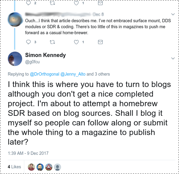
Originally I had not planned to blog about this build but a post on Hackaday bought forth some comments on Twitter:
Consequently, I couldn't really not blog about this project. I could say that all the individual parts of this project are simple enough but I frequently come across projects or circuits that leave out descriptions of a 'simple' part of the circuit because the experienced builder just cannot believe that not everybody knows what they know. Consequently, I will try to explain each section as I go along or provide a link to a resource on the Internet that does a much better job of describing it than I ever could. All components except the ADE-1 are through hole components and I will build Manhattan style. The ADE-1 can (just) be mounted in this way. After I complete this project I would like to try to build the same circuits using only SMD parts as a follow up. My choice of the STM32F746-Discovery board is mainly because I have one here. It costs about $55 and, although there does seem to be a bit of a lead time in the UK at the moment (December 2017), it is still in production and is fantastic value for money. It contains an ARM Cortex-M7 microprocessor, ADC's (analogue-digital controller), DAC's (digital-analogue controller), ethernet, micro-SD card interface, audio line-in/out and a 4.3" colour LCD-TFT screen with capacitive touch input among other features. You'd be hard pressed to find a 4.3" capacitive touch LCD alone for the same price on e-bay. If I hadn't found that ST have recently licenced DSP Concepts Audio Weaver software for use royalty-free on ST devices this project wouldn't be going ahead but the Audio Weaver software is fantastic. It will enable me to design the software audio processing parts of the solution on a PC (sadly it doesn't work on Linux, even under Wine) and tune these in real time while they are deployed to the STM32F746 device. When the tuning is completed the code can be deployed standalone to the microcontroller. In fact, at the moment I think that the hardest part of this whole project is going to be building the graphical user interface, for which I will use STemWin, another piece of software that ST licence for their customers to use royalty-free. What will you need if you plan to join in with me in this project? I am going to make the assumption that you have built some electronic circuits or kits before, firstly I'll build the RF components that produce the I/Q outputs that will be fed into the STM32F746: Soldering iron and other tools you use to build circuits Several pieces of single sided copper clad board like this MeSquares to enable Manhatten style construction RG174 or similar thin co-axial cable to link the RF stages Si5351 breakout board, available from Adafruit and other resellers 74HC74 D-type flip flop 2 x ADE-1-24 frequency mixers or the non-SMD but more expensive equivalent (SBL-1) A handful of 2N3904 transistors There will also be some resistors, capacitors and ferrite cores required that I will detail as I go along. The STM32F746-Discovery board from your favourite electronics reseller, Farnell & RS stock them in the UK amongst others or direct from ST If you already have an oscilloscope with FFT function then I suggest you build a wideband RF noise generator which will be useful to test the RF amp and bandpass filter. I built one like this because it uses the ubiquitous 2N3904 transistors but many designs are available on the web.
Finally, a warning. This will be a learn as you go along project and if you follow along you need to be prepared to trouble shoot and fault find. As it stands at the moment I believe that it will be possible to build a transceiver as described above. What I do know is that we will all learn something and prove that not all of us are "Radio Amateuring like it's 1975"! Next post: The RF amp.
The rotary encoder control works by switching between screen buttons on each push of the encoder button. The button that is activated is highlighted in blue when active, non-buttons that have actions are highlighted in red. Turning the encoder clockwise or anti-clockwise will change the option and activate it immediately. When the station name is red you can tune manually (the station name will change to 'User' after the frequency has been changed). Having reviewed my code it is difficult to describe in detail exactly which changes need to be made to add rotary encoder control. However, as far as I am aware I have put a comment including the word 'rotary' in every place where I have added code for this reason. If you want to backport the rotary encoder code to the STM32F4 board I suggest you search all the code for the word 'rotary' - grep -r rotary * - and take it from there. There are three main additions of code to support the rotary encoder. There is a:
new routine in SDR_initPeriphs.c called initEncoder()
new routine in main.c called ManageEncoder()
new routine in stm32f7xx_hal_msp.c called HAL_TIM_Encoder_MspInit()
an additional section in the HAL_GPIO_EXTI_Callback routine in stm32f7xx_it.c
Elsewhere various variables are defined in main.h and Globals.h.
Adding the external LCD involved a lot of digging around in low level LCD controller code. It must have affected my brain because now I cannot see what I changed to make it work. There's some pin definitions for the LCD in main.h, maybe that's all it needs but I am sure the STemWin GUI controller is defined somewhere. If you want to look into this area then the file LCD_X_8080_8.h would be a good place to start. A video of the rotary encoder/LCD combination will be posted here shortly. The code is available on github link
This post assumes that the RF pre-amp and audio out circuits have been built as described by I2PHD in his original paper found under the ARM Radio section of his website. Microprocessor - STM32F746-Nucleo board. LCD - ILI9341 driver, looks the same as this one Rotary encoder with integrated push switch My code uses the following pin connections: Component Pin STM32F746 Pin LCD_D0 PC0 LCD_D1 PC1 LCD_D2 PC2 LCD_D3 PC3 LCD_D4 PC4 LCD_D5 PC5 LCD_D6 PC6 LCD_D7 PC7 LCD_RST PE2 LCD_CS PE3 LCD_RS PE4 LCD_WR PE5 LCD_RD PE6 Rotary encoder clockwise PB4 Rotary encoder anti-clockwise PB5 Rotary encoder centre GND Rotary encoder push button PA0 RF In PA3 Audio Out PA4 In the next post I will describe the code I have added to support the rotary encoder functionality as well as the changes to the screen layout. The cide is available on github link
Alberto, I2PHD, developed a VLF to MF receiver entirely in a microprocessor utilising the STM32F4 Discovery board. I was intrigued by this so I purchased a STM32F746 Discovery board. The F7 board uses the faster ARM Cortex M7 processor rather than the M4 processor used in the STM32F4 range of boards.
However, I soon found that the STM32F7 Disco board does not make the same GPIO pins available to use. Specifically only the third analogue-digital converter (ADC3) of three is available to use. Alberto's design uses ADC's 1 & 2 in double buffered mode and this approach is fundamental, consequently I realised that I would not be able to use this board for the receiver. By the time I had worked this out ST had released the STM32F746-Nucleo board, this board is similar to the Discovery board except it makes all the GPIO pins available to use but it does not have a built in LCD display.
I was not able to compile the source code written for the F4 board for the F7 board. Whether this was through my lack of experience or for some other reason I do not know as the code is meant to be compatible between the two devices. Subsequently, I proceeded to rewrite the code to use the Hardware Abstraction Layer (HAL) provided by ST. Due to the fragmented and incomplete nature of documentation for the HAL a great deal of experimentation and trial & error was involved. However, this did mean that my understanding of C programming for embedded microprocessors and associated debugging using gdb increased quickly.
Currently the status of this project is as follows:
Code for STM32F4 ported to work with the STM32F7 devices using HAL firmware library version 1.3.0*
To overcome the lack of an LCD on the Nucleo board an inexpensive LCD was purchased on ebay which uses the ILI9341 LCD controller and this was integrated into the code.
To overcome zero documentation on how to use the touch screen capabilities of the LCD I bought I implemented control using a rotary encoder.
I have added a spectogram function which shows a display of the signals being received - this is a work in progress.
* I have looked at using the newer 1.5.1 HAL firmware but there have been significant changes made to the operation of some of the functions and I don't intend to rewrite the code to handle these at the moment.
The picture at the top of this post shows the receiver receiving the MSF time signal on 60kHz.
I plan a series of blog posts to document this project. My plan is for posts covering the following topics:
Setting up the development environment - using Eclipse IDE, GCC compiler, OpenSTM32, gdb.
My implementation and the hardware connections, particularly covering the LCD and rotary encoder.
Specifics around the rotary encoder control and the LCD.
The spectogram function.
Wrap-up, including some problems I have yet to overcome.
Picture of the video of my garden transmitted by my HackRF Blue
In the UK much digital amateur television (DATV) is transmitted using the DVB-S standard. This is the standard used in Europe to transmit standard definition satellite television. Eventually I aim to transmit video through my local DATV repeater. What I have done is to prove the feasibility of using a HackRF Blue to act as the radio frequency part of the system. I have drawn a diagram showing the individual components I used and I will go on to describe each in more detail.
Camera I have used a standard DV video camera (Canon MV450i). It is possible to substitute this for a standard webcam. Computer I use a 4 core Intel Core i5-2400, 3.10GHz CPU with 4Gb of memory. Operating system is xubuntu 14.04. dvgrab This software is used to grab the DV stream from the Firewire port that the DV camera is connected to. If you use a webcam then it is not necessary to use this program. It can be installed from the Ubuntu Software Centre or via the Kino pages. ffmpeg ffmpeg is used to convert the raw video stream grabbed by dvgrab into an MPEG-2 transport stream. If you are using a webcam you will need to change the parameters for the input source and the input video codec. It can be installed from the Ubuntu Software Centre or from the ffmpegsite. The output from ffmpeg is sent to a fifo file to be consumed by the gnuradio program. gnuradio I have gnuradio installed via pybombs and am currently running version 3.7.7. Ron Economos has written the gnuradio blocks to enable DVB-S to be transmitted. You will need to download & install these from github. Included in the download is a gnuradio-companion flowgraph. Open this in gnuradio-companion to verify that you have installed the DVB-S gnuradio blocks in the correct place. If blocks show up as red then you haven't. However, Ron's code does not use a HackRF so I have changed the output sink to be a HackRF. You may also want to change the input to be a mpeg-2 transport stream file for testing and/or to reflect the location of the fifo file on your system. You can download my HackRF version of the transmit program from hereand edit it to change the reference to the directory I used for my fifo file to the one on your machine. Example commands One off commands
mkdir ~/dvb-s
cd ~/dvb-s
mkfifo mpeg2.fifo
Command to run dvgrab and ffmpeg
cd ~/dvb-s dvgrab - | ffmpeg -re -thread_queue_size 1000 -i /dev/stdin -vcodec rawvideo -f alsa -i hw:0,0 -acodec mp2 -s 640x480 -r 25 -b:v 2M -minrate:v 2M -maxrate:v 2M -bufsize:v 1.4M -ac 2 -b:a 48k -mpegts_transport_stream_id 1025 -mpegts_service_id 1 -mpegts_pmt_start_pid 0x0fff -mpegts_start_pid 0x0121 -muxrate 2M -f mpegts -y mpeg2.fifo I suspect that some of these parameters are surplus to requirements but these are what worked for me. To use a webcam remove "dvgrab - |" from the start of the line andsubstitute "-i /dev/stdin -vcodec rawvideo" with "-i /dev/video0 -vcodec mpeg2video" To test that this step is working you can use mplayer to consume the video feed from the fifo file: mplayer mpeg2.fifo To transmit the video stream open another terminal window cd ~/dvb-s ./dvbs_tx_hackrf.py
The transmission looks like this when received by gqrx on another HackRF.
How to receive the signal. I used a standard DVB-S satellite TV receiver. However, these use an LNB which mixes the 10/11GHz signal with a 9750 MHz (or 10700 MHz) local oscillator (LO) to produce a signal around 1000-1250 MHz. In this case we do not use the LNB but connect an antenna directly to the input port where the LNB usually connects. WARNING: the antenna port has 13/18 Volts on the centre core. Do not allow your makeshift antenna to short across the inner and outer of the antenna port or you may damage your receiver. In my example I have the HackRF Blue transmitting on 1000 MHz. I set the receiver to receive on 10750 MHz. As the LO is at 9750 MHz, 9750 plus 1000 = 10750. You need to know the LO your LNB is using (it is normally marked on them or try both values). So, I set the satellite receiver to scan for a signal on 10750 MHz. The other value the receiver needs to know is the symbols/second value. In the gnuradio program I have set it to 2 million symbols/second. Most satellite receivers will receive a minimum of 2m sym/sec, and this is the value you need to set in the receiver (or 2000k sym/sec). FEC can also be specified but my receiver set this to 'AUTO'. Antenna My satellite receiver is located underneath the television in an adjacent room to my study. Due to the use of a dummy load the transmission can only be received if the antenna from the satellite receiver is close to the dummy load. I used a length of satellite co-axial cable long enough to reach between both rooms, terminated one end with a F-type plug to fit the antenna socket of the satellite receiver. At the other end I connected the inner core of the co-ax to the driven element of a 1296 MHz beam I made recently. The outer core I taped up with insulating tape to ensure that it was not going to short to the inner conductor. I haven't tried this but if you expose 7.5 cm of the centre conductor having cut back the outer sheath, the outer shield of copper and the inner dielectric (taking care not to short the inner and outer conductors) this should work as a quarter wave antenna at 1000 MHz. You will probably have to hold it very close to the dummy load connected to the HackRF Blue to receive the signal. WARNING: Wrap the centre conductor you expose in insulating tape to prevent accidental shorting as there is still 13/18V on the centre conductor. With my 23 cm beam pointing at the dummy load I was able to receive the signal about 5 metres away. References
Explanation of the ffmpeg parameters here and here. Details of transmitting DVB-T using a webcam here.
Legal advisory It is illegal to transmit on radio frequencies for which you do not possess a valid licence issued by your government. I hold an amateur radio licence so am allowed to transmit on a set of defined frequencies. However, for this experiment I transmitted into a dummy load, meaning that the transmission was not radiated more than about 3 metres. For more information on becoming a radio amateur please contact your national amateur radio organisation. See the list here. The small print If some or other part of this doesn't work for you please don't send me a curt email saying "It doesn't work". It works for me on my system so try and understand why it doesn't work and adapt it to your environment.