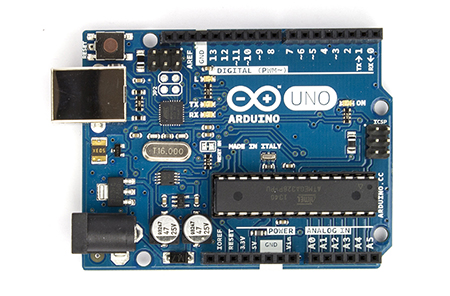
I recently got an Arduino Uno. The glut of cheap AD9850 boards on e-bay made one an obvious first purchase to complement the Arduino. I made an Arduino and AD9850 VFO which was a good learning experience but I didn't have any immediate need for a VFO.
I have been wondering about the efficiency of my HF antennas recently and I fired up WSPR
on my pc one day. Immediately I realised that an Arduino and AD9850 powered WSPR transmitter would be possible.
Of course, someone had published a similar project on the Internet. George Smart, M1GEO, has posted a project on his web pages describing an Arduino based AD9851 WSPR transmitter. However, there are some crucial differences between the two chips and I also found that George's Arduino code didn't work well with the GPS I was using.
So, my project is based heavily on M1GEO's, but with additional help and information provided by other web pages. My own contribution is largely in enhancing the Arduino code and integrating the project from various sources.
Challenge #1 - accurate timing
WSPR relies on stations starting to transmit between seconds 1 and 4 of even minutes. Consequently an accurate time source is necessary. I already had a GPS 'puck' and it is a trivial task to connect a GPS to the Arduino using the TinyGPS library. However, the Arduino is expecting a TTL level signal from the GPS and my device outputs RS-232. Hence, a converter between the two voltage levels is required. Fortunately there is a handy chip that does this called the MAX232. Connecting this between my GPS and the Arduino meant that I was able to use the TinyGPS library to receive the NMEA sentences from the GPS. If you use a GPS module like the one described in this article, you will not need the MAX232 chip.
Challenge #2 - differences between the AD9851 and AD9850
There are two main differences to be aware of. Firstly, the AD9850 has a different oscillator frequency, it uses 125Mhz whereas the AD9851 uses 180Mhz. Secondly, the AD9850 requires a different set of pins to be set HIGH to enable serial mode, ie. to be able to write data to it serially rather than in parallel. Pins RESET, CLOCK and LOAD all have to be set HIGH (pins labelled RESET, H_CLK and FU_UD respectively on my DDS module).
Challenge #3 - switching an amplifier
The output from the DDS module is very low. I am feeding this to a QRP HF amplifier which generates around 250mW. However, I needed to switch the amp on and off in line with the times when the WSPR signal was being transmitted. It is easy to set a pin on the Arduino to HIGH at the start of the transmission sequence and to use this to drive a transistor switch connected to a relay, as described here. The relay switches the power to the amp on and off.
Challenge #4 - generating more power from the HF amplifier
To be continued, my amplifiers never seem to be able to output more than a couple of hundred milliwats so I need to do some more work here.
Challenge #5 - building an effective low pass filter
A low pass filter is essential to ensure no harmonics are transmitted. I've not had much success building these either so am going to
Arduino Sketch
The Arduino sketch I have modified and that works for the AD9850 and my GPS can be downloaded from here. You will need to generate the WSPR tones as described in M1GEO's post here and amend the sketch with tones specific to your callsign, location and power level. If you use this version please add a line to turn off the GPS interrupts during the WSPR tx period, add 'ss.end();' between lines 141 and 142.
I have since added a 4 line by 20 character I2C LCD display. I have also fixed the timing issue that didn't seem to occur without the LCD but is caused by interrupts from the GPS delaying the internal clock thus making it useless for WSPR. The updated version can be downloaded here.
Note: you will also need to download and install a few libraries:
If you open the Arduino serial monitor when the sketch is running you will see the timing string from the GPS and when the WSPR tx is activated.
Here is a picture of my Arduino Uno, AD9850 DDS board and breadboard with the MAX232 chip and amplifier power switching circuit - ugly at the moment but it works.


None of those sketches verify properly.
ReplyDeleteApologies, I didn't include details of the libraries required. You will need to download and install the following Arduino libraries:
Delete- Encoder - http://www.pjrc.com/teensy/td_libs_Encoder.html
- LiquidCrystal_I2C - http://hmario.home.xs4all.nl/arduino/LiquidCrystal_I2C/
- TinyGPS - http://arduiniana.org/libraries/tinygps/
References to the rotary library (#include ) can be commented out.
I have tested the sketches linked to on this page and, with the libraries installed and the reference to the rotary library commented out or removed, both compile under Arduino IDE versions 1.0.5 and 1.6.3.