Meteor M-N2 Images

Showing posts with label wspr. Show all posts

Tuesday, 3 June 2014

WSPR comparison between Inverted-L and G5RV

WSPR spots using 5W on 20m with my Inverted-L

I managed to get wsprx working in receive mode on my new installation of Linux Mint 16. The realtime waterfall makes it much easier to ensure that your radio is accurately set to receive in the wspr sub-band. I found that my FT920 reads about 40Hz low as a result. However, it crashes when coming out of transmit mode. Consequently, I installed the older version wspr 2.0. This also had a problem with one of the Python libraries but there was a fix documented on the wsprnet.org website.

The waterfall used in wsprx

This means that I can now run wspr with a little more power than previously, my broadband HF amplifier only produces about 0.5W. I have been wspr'ing with 5W and the results using my new inverted-L you can see in the screenshot at the top of the page. I am amazed at how far 5W will reach. However, it is a little too easy, on my first transmission my signal was received by KK7UQ on the west coast of the USA.

After an hour wspr'ing on the inverted-L I switched to my G5RV and the difference is considerable. Although the G5RV is higher than the inverted-L (around 12m versus 6m high) one leg runs E-W and the other leg NW-SE. The inverted-L runs SE-NW pointing directly at north America. The resulting wspr spots from the G5RV are below.

WSPR spots using 5W on 20m with my G5RV

Interestingly I received VK3HAD equally well on both antennas and KK7UQ received me equally well until dusk fell when a few more US stations heard me and were heard by me. 

Along the greyline I was heard by ZL3DMH at 19016km distance.

This isn't a scientific test, by any stretch of the imagination but very interesting none the less. However, what it has shown me is that 5W and wire antennas equals QRO in wspr terms!

Monday, 26 May 2014

Inverted L and results from WSPR


Good results with my new Inverted-L overnight. Running 500mW I got multiple decodes from the stations you can see on the map above.

The tx is the same homebrew amplifier that I have used previously so the antenna is the only item I have changed. With my other antenna, a G5RV, I had only been received once in the USA.

Overall this confirms my initial findings that the Inverted-L pointing at north America is performing very well.

Saturday, 15 March 2014

Multi-function AD9850 MEPT with WSPR, QRSS & Sequential Multi-Tone Hellschreiber (GPS & ntp versions)

My QRSS and SMT-Hell signals received by the PA9QV grabber on 40m

Building on my Arduino & AD9850 powered WSPR transmitter I have extended the code to also transmit QRSS CW and Sequential Multi-tone Hellschreiber.

The three modes are transmitted in sequence, although WSPR takes precedence. The tx cycle is something like this:
- WSPR
- QRSS
- WSPR
- SMT-Hell
- WSPR
- QRSS
etc.

I have had a problem where my GPS was not getting a fix and so I was not able to get the correct time for the WSPR transmissions. Consequently, I have created two versions of the sketch. One uses a GPS for its time source and the other uses the Internet Network Time Protocol (ntp). The ntp version requires an Arduino Ethernet shield and Internet connection.

I have learnt a huge amount about Arduino programming while working on this. However, I am going to stop tinkering with the programming now and use it to test out some different antennas.

The enhanced GPS sketch can be downloaded from here and the ntp version from here.
Note: you will also need to download and install a few libraries:


The alphabet in Sequential Multi-tone Hellschreiber,
monitored on my receiver.


There are three places that variables need to be changed in the sketch. These are:

QRSS frequency:
//***************Adjust this frequency to position your signal in the band
//*****************
#define QRSS_IDLE    10.139870e6

WSPR tones:
//*******************Create the WSPR tones for your callsign/qth/power using the instructions
//*******************on M1GEO's website http://www,george-smart.co.uk/wiki/Arduino_WSPR
//HOME: G0FCU 24dbm (300mw 24dBm)
/* static byte WSPR_DATA_HOME[] = {3,3,2,0,0,0,2,2,1,2,0,0,1,1,1,2,2,2,1,2,2,3,0,3,

QRSS/SMT-Hell text:
//******************enter your callsign in the next two variables, replacing the 'xxxxx'
//******************The callsign_hell can contain '/' or space as well as a locator
char callsign[]="G0FCU"; //callsign to send in QRSS mode
char callsign_hell[]="G0FCU/IO91SE"; //text to send in SMT-Hell mode


Tuesday, 31 December 2013

Arduino & AD9850 based WSPR transmitter - continued

Arduino & AD9850 based WSPR transmitter - continued


I have been improving the WSPR transmitter. I noticed that when setting it to transmit every other minute the code did not actually work. I think this was because after the tx period had ended the time that was in the serial buffer from the GPS was from before the tx period started. This consequently caused all sorts of problems.

There is no way to flush the serial buffer so I solved this by reading the time from the GPS for 1000ms after the tx period has completed. This allows the stale time to be read and discarded and the up-to-date time to be captured. After this 1000ms period a variable is reset to change the read time of the serial buffer back to 250ms.

The other significant change I have made is to what happens when the tx period has ended but it is not required to transmit in the subsequent 2 minute period. In the old version this was implemented crudely by using a delay of 5 seconds. This actually doesn't work because the tx period ends at around 51 seconds of the odd minute. Thus the delay actually needs to be around 15 seconds, to 5 seconds past the even minute to miss the tx period. I have now implemented this in code, this means that I can start to think about implementing a web based front end.

I don't intend to replace the delay of 682ms used to transmit each WSPR tone at the moment. As this is so time critical I will avoid it for now!

The code for the latest version (v6) can be downloaded here.
Note: you will also need to download and install a few libraries:


I made a homebrew Arduino shield incorporating the AD9850, the MAX232 chip and relay to switch the amplifier on, as shown below.


Sunday, 6 October 2013

Arduino and AD9850 WSPR Transmitter


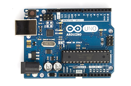
I recently got an Arduino Uno. The glut of cheap AD9850 boards on e-bay made one an obvious first purchase to complement the Arduino. I made an Arduino and AD9850 VFO which was a good learning experience but I didn't have any immediate need for a VFO.

I have been wondering about the efficiency of my HF antennas recently and I fired up WSPR
on my pc one day. Immediately I realised that an Arduino and AD9850 powered WSPR transmitter would be possible.

Of course, someone had published a similar project on the Internet. George Smart, M1GEO, has posted a project on his web pages describing an Arduino based AD9851 WSPR transmitter. However, there are some crucial differences between the two chips and I also found that George's Arduino code didn't work well with the GPS I was using.

So, my project is based heavily on M1GEO's, but with additional help and information provided by other web pages. My own contribution is largely in enhancing the Arduino code and integrating the project from various sources.

Challenge #1 - accurate timing

WSPR relies on stations starting to transmit between seconds 1 and 4 of even minutes. Consequently an accurate time source is necessary. I already had a GPS 'puck' and it is a trivial task to connect a GPS to the Arduino using the TinyGPS library. However, the Arduino is expecting a TTL level signal from the GPS and my device outputs RS-232. Hence, a converter between the two voltage levels is required. Fortunately there is a handy chip that does this called the MAX232. Connecting this between my GPS and the Arduino meant that I was able to use the TinyGPS library to receive the NMEA sentences from the GPS. If you use a GPS module like the one described in this article, you will not need the MAX232 chip.

Challenge #2 - differences between the AD9851 and AD9850

There are two main differences to be aware of. Firstly, the AD9850 has a different oscillator frequency, it uses 125Mhz whereas the AD9851 uses 180Mhz. Secondly, the AD9850 requires a different set of pins to be set HIGH to enable serial mode, ie. to be able to write data to it serially rather than in parallel. Pins RESET, CLOCK and LOAD all have to be set HIGH (pins labelled RESET, H_CLK and FU_UD respectively on my DDS module).

Challenge #3 - switching an amplifier

The output from the DDS module is very low. I am feeding this to a QRP HF amplifier which generates around 250mW. However, I needed to switch the amp on and off in line with the times when the WSPR signal was being transmitted. It is easy to set a pin on the Arduino to HIGH at the start of the transmission sequence and to use this to drive a transistor switch connected to a relay, as described here. The relay switches the power to the amp on and off.

Challenge #4 - generating more power from the HF amplifier

To be continued, my amplifiers never seem to be able to output more than a couple of hundred milliwats so I need to do some more work here.

Challenge #5 - building an effective low pass filter

A low pass filter is essential to ensure no harmonics are transmitted. I've not had much success building these either so am going to work on this next. buy an LPF kit from Hans Summers, G0UPL For £2.50 you can't really go wrong. I bought filters for 20m and 30m so at some point I will implement antenna switching as well.

Arduino Sketch

The Arduino sketch I have modified and that works for the AD9850 and my GPS can be downloaded from here. You will need to generate the WSPR tones as described in M1GEO's post here and amend the sketch with tones specific to your callsign, location and power level. If you use this version please add a line to turn off the GPS interrupts during the WSPR tx period, add 'ss.end();' between lines 141 and 142.

I have since added a 4 line by 20 character I2C LCD display. I have also fixed the timing issue that didn't seem to occur without the LCD but is caused by interrupts from the GPS delaying the internal clock thus making it useless for WSPR. The updated version can be downloaded here.

Note: you will also need to download and install a few libraries:

If you open the Arduino serial monitor when the sketch is running you will see the timing string from the GPS and when the WSPR tx is activated.

Here is a picture of my Arduino Uno, AD9850 DDS board and breadboard with the MAX232 chip and amplifier power switching circuit - ugly at the moment but it works.