Meteor M-N2 Images

Showing posts with label arduino. Show all posts

Monday, 16 June 2014

Arduino Antenna Analyser

Inverted-L SWR plot

The alternative title for this post could be "Even more fun with antennas"! 

I know that the inverted-L that I erected recently resonates on the bands that I wanted it too (i.e. 10/14/18Mhz) but tuning wire antennas to resonance always involves a lot of running between ends of the antenna and rig, taking notes of SWR achieved at specific frequencies and working out whether to shorten or lengthen the wire. 

An antenna analyser can help reduce some of this effort as you get a graph of SWR plotted against frequency. However, these cost upwards of £200. Now bring to the table the ubiquitous Arduino, my favourite 'toy' tool of the moment.

I found several designs for antenna analysers based on Arduino's but I think it was someone on Twitter who pointed me to the design by K6BEZ. If you have an Arduino and a few resistors this is really cheap to make. I had to buy the diodes and the op-amp, but these cost me less than £10 on e-bay with an op-amp and about 10 diodes to spare.

Fortunately I also found Matt Gumbley's website and Matt has designed a Veroboard layout for the K6BEZ circuit. This made building the circuit very simple and it worked first time for me. I didn't have any 50 ohm or 648 ohm resistors so I used a 27R and 22R in series (49R) in place of the 50R resistors and a 470R & 180R in series (650R) in place of the 648R resistors.

Setting the frequency range to scan involves entering the commands below via the Arduino serial monitor. The key commands in the Arduino sketch are:
  • frequencyA - set the frequency to start the scan from, in Hz.
  • frequencyB - set the frequency to end the scan at, in Hz.
  • stepsN - set the number of steps for the scan
  • ? - displays the parameters that have been set
  • S or s - start the scan
e.g. 12000000A sets the start frequency to 12Mhz.

For a 1Mhz to 30Mhz scan I use 2000 steps.

The results are returned to the serial monitor and in the default sketch are:
  • frequency,0,swr,forward voltage, reverse voltage
To get the graphs shown here I have simply copied the data into a spreadsheet, converted the frequency to MHz by dividing by 1000000, and divided the SWR by 1000. I have then used gnuplot to create the graphs.

The gnuplot commands I used are:
set term canvas size 600,400
set output "g5rv.html"
set linetype 1 lw 1 lc rgb "blue" pointtype 0
set xlabel 'Frequency (MHz)'
set ylabel 'SWR'
set xtics scale 2,1
set mxtics 5
plot 'data' smooth bezier title 'G5RV antenna'

Line 2 sets the output filename  to 'g5rv.html'.
Line 8 loads the data from a file called 'data' (frequency and swr, one pair of data values per line, separated by a space) and give the output the title 'G5RV antenna'.

G5RV SWR plot
5 MHz dipole SWR plot

What this shows me is that my G5RV resonates slightly higher in frequency than the 80m & 40m amateur bands but that my 5 MHz dipole and the Inverted-L resonate exactly where I want them to.

Even better is that I have got an antenna analyser for less than the price of a pint of beer. Cheers!

Saturday, 15 March 2014

Multi-function AD9850 MEPT with WSPR, QRSS & Sequential Multi-Tone Hellschreiber (GPS & ntp versions)

My QRSS and SMT-Hell signals received by the PA9QV grabber on 40m

Building on my Arduino & AD9850 powered WSPR transmitter I have extended the code to also transmit QRSS CW and Sequential Multi-tone Hellschreiber.

The three modes are transmitted in sequence, although WSPR takes precedence. The tx cycle is something like this:
- WSPR
- QRSS
- WSPR
- SMT-Hell
- WSPR
- QRSS
etc.

I have had a problem where my GPS was not getting a fix and so I was not able to get the correct time for the WSPR transmissions. Consequently, I have created two versions of the sketch. One uses a GPS for its time source and the other uses the Internet Network Time Protocol (ntp). The ntp version requires an Arduino Ethernet shield and Internet connection.

I have learnt a huge amount about Arduino programming while working on this. However, I am going to stop tinkering with the programming now and use it to test out some different antennas.

The enhanced GPS sketch can be downloaded from here and the ntp version from here.
Note: you will also need to download and install a few libraries:


The alphabet in Sequential Multi-tone Hellschreiber,
monitored on my receiver.


There are three places that variables need to be changed in the sketch. These are:

QRSS frequency:
//***************Adjust this frequency to position your signal in the band
//*****************
#define QRSS_IDLE    10.139870e6

WSPR tones:
//*******************Create the WSPR tones for your callsign/qth/power using the instructions
//*******************on M1GEO's website http://www,george-smart.co.uk/wiki/Arduino_WSPR
//HOME: G0FCU 24dbm (300mw 24dBm)
/* static byte WSPR_DATA_HOME[] = {3,3,2,0,0,0,2,2,1,2,0,0,1,1,1,2,2,2,1,2,2,3,0,3,

QRSS/SMT-Hell text:
//******************enter your callsign in the next two variables, replacing the 'xxxxx'
//******************The callsign_hell can contain '/' or space as well as a locator
char callsign[]="G0FCU"; //callsign to send in QRSS mode
char callsign_hell[]="G0FCU/IO91SE"; //text to send in SMT-Hell mode


Tuesday, 31 December 2013

Arduino & AD9850 based WSPR transmitter - continued

Arduino & AD9850 based WSPR transmitter - continued


I have been improving the WSPR transmitter. I noticed that when setting it to transmit every other minute the code did not actually work. I think this was because after the tx period had ended the time that was in the serial buffer from the GPS was from before the tx period started. This consequently caused all sorts of problems.

There is no way to flush the serial buffer so I solved this by reading the time from the GPS for 1000ms after the tx period has completed. This allows the stale time to be read and discarded and the up-to-date time to be captured. After this 1000ms period a variable is reset to change the read time of the serial buffer back to 250ms.

The other significant change I have made is to what happens when the tx period has ended but it is not required to transmit in the subsequent 2 minute period. In the old version this was implemented crudely by using a delay of 5 seconds. This actually doesn't work because the tx period ends at around 51 seconds of the odd minute. Thus the delay actually needs to be around 15 seconds, to 5 seconds past the even minute to miss the tx period. I have now implemented this in code, this means that I can start to think about implementing a web based front end.

I don't intend to replace the delay of 682ms used to transmit each WSPR tone at the moment. As this is so time critical I will avoid it for now!

The code for the latest version (v6) can be downloaded here.
Note: you will also need to download and install a few libraries:


I made a homebrew Arduino shield incorporating the AD9850, the MAX232 chip and relay to switch the amplifier on, as shown below.


Sunday, 6 October 2013

Arduino and AD9850 WSPR Transmitter


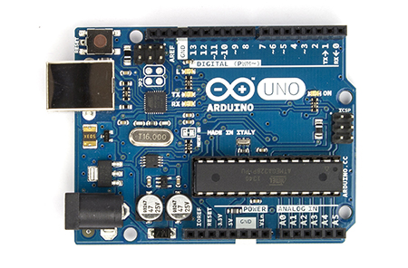
I recently got an Arduino Uno. The glut of cheap AD9850 boards on e-bay made one an obvious first purchase to complement the Arduino. I made an Arduino and AD9850 VFO which was a good learning experience but I didn't have any immediate need for a VFO.

I have been wondering about the efficiency of my HF antennas recently and I fired up WSPR
on my pc one day. Immediately I realised that an Arduino and AD9850 powered WSPR transmitter would be possible.

Of course, someone had published a similar project on the Internet. George Smart, M1GEO, has posted a project on his web pages describing an Arduino based AD9851 WSPR transmitter. However, there are some crucial differences between the two chips and I also found that George's Arduino code didn't work well with the GPS I was using.

So, my project is based heavily on M1GEO's, but with additional help and information provided by other web pages. My own contribution is largely in enhancing the Arduino code and integrating the project from various sources.

Challenge #1 - accurate timing

WSPR relies on stations starting to transmit between seconds 1 and 4 of even minutes. Consequently an accurate time source is necessary. I already had a GPS 'puck' and it is a trivial task to connect a GPS to the Arduino using the TinyGPS library. However, the Arduino is expecting a TTL level signal from the GPS and my device outputs RS-232. Hence, a converter between the two voltage levels is required. Fortunately there is a handy chip that does this called the MAX232. Connecting this between my GPS and the Arduino meant that I was able to use the TinyGPS library to receive the NMEA sentences from the GPS. If you use a GPS module like the one described in this article, you will not need the MAX232 chip.

Challenge #2 - differences between the AD9851 and AD9850

There are two main differences to be aware of. Firstly, the AD9850 has a different oscillator frequency, it uses 125Mhz whereas the AD9851 uses 180Mhz. Secondly, the AD9850 requires a different set of pins to be set HIGH to enable serial mode, ie. to be able to write data to it serially rather than in parallel. Pins RESET, CLOCK and LOAD all have to be set HIGH (pins labelled RESET, H_CLK and FU_UD respectively on my DDS module).

Challenge #3 - switching an amplifier

The output from the DDS module is very low. I am feeding this to a QRP HF amplifier which generates around 250mW. However, I needed to switch the amp on and off in line with the times when the WSPR signal was being transmitted. It is easy to set a pin on the Arduino to HIGH at the start of the transmission sequence and to use this to drive a transistor switch connected to a relay, as described here. The relay switches the power to the amp on and off.

Challenge #4 - generating more power from the HF amplifier

To be continued, my amplifiers never seem to be able to output more than a couple of hundred milliwats so I need to do some more work here.

Challenge #5 - building an effective low pass filter

A low pass filter is essential to ensure no harmonics are transmitted. I've not had much success building these either so am going to work on this next. buy an LPF kit from Hans Summers, G0UPL For £2.50 you can't really go wrong. I bought filters for 20m and 30m so at some point I will implement antenna switching as well.

Arduino Sketch

The Arduino sketch I have modified and that works for the AD9850 and my GPS can be downloaded from here. You will need to generate the WSPR tones as described in M1GEO's post here and amend the sketch with tones specific to your callsign, location and power level. If you use this version please add a line to turn off the GPS interrupts during the WSPR tx period, add 'ss.end();' between lines 141 and 142.

I have since added a 4 line by 20 character I2C LCD display. I have also fixed the timing issue that didn't seem to occur without the LCD but is caused by interrupts from the GPS delaying the internal clock thus making it useless for WSPR. The updated version can be downloaded here.

Note: you will also need to download and install a few libraries:

If you open the Arduino serial monitor when the sketch is running you will see the timing string from the GPS and when the WSPR tx is activated.

Here is a picture of my Arduino Uno, AD9850 DDS board and breadboard with the MAX232 chip and amplifier power switching circuit - ugly at the moment but it works.