Meteor M-N2 Images

Saturday, 15 March 2014

Multi-function AD9850 MEPT with WSPR, QRSS & Sequential Multi-Tone Hellschreiber (GPS & ntp versions)

My QRSS and SMT-Hell signals received by the PA9QV grabber on 40m

Building on my Arduino & AD9850 powered WSPR transmitter I have extended the code to also transmit QRSS CW and Sequential Multi-tone Hellschreiber.

The three modes are transmitted in sequence, although WSPR takes precedence. The tx cycle is something like this:
- WSPR
- QRSS
- WSPR
- SMT-Hell
- WSPR
- QRSS
etc.

I have had a problem where my GPS was not getting a fix and so I was not able to get the correct time for the WSPR transmissions. Consequently, I have created two versions of the sketch. One uses a GPS for its time source and the other uses the Internet Network Time Protocol (ntp). The ntp version requires an Arduino Ethernet shield and Internet connection.

I have learnt a huge amount about Arduino programming while working on this. However, I am going to stop tinkering with the programming now and use it to test out some different antennas.

The enhanced GPS sketch can be downloaded from here and the ntp version from here.
Note: you will also need to download and install a few libraries:


The alphabet in Sequential Multi-tone Hellschreiber,
monitored on my receiver.


There are three places that variables need to be changed in the sketch. These are:

QRSS frequency:
//***************Adjust this frequency to position your signal in the band
//*****************
#define QRSS_IDLE    10.139870e6

WSPR tones:
//*******************Create the WSPR tones for your callsign/qth/power using the instructions
//*******************on M1GEO's website http://www,george-smart.co.uk/wiki/Arduino_WSPR
//HOME: G0FCU 24dbm (300mw 24dBm)
/* static byte WSPR_DATA_HOME[] = {3,3,2,0,0,0,2,2,1,2,0,0,1,1,1,2,2,2,1,2,2,3,0,3,

QRSS/SMT-Hell text:
//******************enter your callsign in the next two variables, replacing the 'xxxxx'
//******************The callsign_hell can contain '/' or space as well as a locator
char callsign[]="G0FCU"; //callsign to send in QRSS mode
char callsign_hell[]="G0FCU/IO91SE"; //text to send in SMT-Hell mode


Tuesday, 4 March 2014

First try with QRSS

QRSS

My QRSS signal


Items #3 & #4 on my 'Things to do in my 30th Year as a Radio Amateur' were to have a go at QRSS.

The article by Ian Liston-Smith, G4JQT, in the February 2014 edition of Practical Wireless was instrumental in spurring me into action on this activity.

I had a look round the Internet and found several pieces of software that are specifically designed to receive QRSS signals. They were Argo, QRSS-VD and LOPORA.

I run Ubuntu Linux on my pc and setting anything up to run with sound cards always seems to be a little difficult (or maybe it's me).

I got Argo working quickly but it is a Windows program running on Linux so I spent some time getting QRSS-VD working. It is written in Python so will also work on Windows. It works well but the key to it was changing the bandpass low and high settings to ensure that the QRSS sub-band was being decoded. I haven't yet got LOPORA to work with my sound card yet.

The QRSS-VD website has comprehensive instructions on how to set up and use it, most of which I haven't yet read!


An example of decoding QRSS using QRSS-VD.

In summary I feel that QRSS combines the technology of receiving QRPp signals using the power of your computer to decode them (along the lines of WSPR) with the beauty of being able to decode them yourself.

In practice, combining QRSS and WSPR is a great way to analyse propagation and antenna performance. I have amended my Arduino/AD9850 based WSPR transmitter so that it transmits alternatively between WSPR and QRSS. More of this in a future blog post.


Tuesday, 25 February 2014

Thirty Years a Radio Amateur

Celebrating Thirty Years as a Radio Amateur, 1984-2014

My FT-817 on top of my original TR-9130, from a 2m only rig in 1984
to an HF to UHF rig in 2014.

My first contact was on 7th September 1984 with G1/PD0HWL/M on 2m. He was only a few miles from me but I hadn't managed to work out the use of the RF Gain control on my newly purchased Trio TR-9130 and I had it turned all the way down. Velerh probably wondered why I gave him a 33 report when he gave me a 59! By the time I had my second QSO two days later with G1EXO I had worked it out and 59 reports were exchanged both ways.

My early ham radio exploits were predominantly with a group of amateurs I met after I left college and moved to Stevenage in Hertfordshire, these included G0HOP, G6LMV, G1IFL, and G1LIQ among others.

That group of Stevenage amateurs ran the G4VAT contest group. I participated in many VHF/UHF contests with them, which were great fun. On one occasion the brakes on my old Mk 1 Vauxhall Cavalier failed on the way up the hill we used top operate from at Pegsdon. This site conveniently had a pub called the 'Live and Let Live' located at the bottom of the hill.

I have found in my log book details of a contact through the OSCAR-13 satellite with JA1CG on 14/8/88. In that same session I had first contacted two German stations. I am pleased to see that Haruo is still active. This was a 145/433 Mhz contact and I remember that G0HOP was instrumental in working out that the satellite would be on the horizon so we would be able to make contacts with our horizontally polarized beams (with no elevation control).

I have been somewhat less active since marriage and children (1999 and 2002/2004 respectively) but I did use the proceeds of a very generous bonus to purchase a Yaesu FT-920 HF rig.

So, what am I gong to do to celebrate this anniversary. Well, I am going to try a few different amateur radio activities, here's the start of a list, that may grow or reduce over the year:

  • Have a JT65B QSO - I have completed this and was very non-plussed by it. I don't think this is a mode for me. I've had a few more JT65 contacts now and will probably have more.
  • Run WSPR to test antenna configurations - I built an Arduino WSPR system last year and see WSPR as ideal for learning about propagation and antennas.
  • Receive QRSS signals - I've done this recently so will blog about it soon. Update: see here
  • Amend my Arduino WSPR system to also transmit QRSS. I've done this, and also added transmission of Sequential Multi-tone Hellschreiber. Update: see here
  • Build a 70Mhz amplifier - I completed my 70Mhz transverter last year, it outputs about 50mW so I need an amplifier to make it useful. I've rebuilt my 70Mhz transverter using a Manhatten style, it now outputs a good 100mW. I've decided not to build an amplifier but to buy one pre-built. I'll do a blog post on this when it is complete and working. However, I did manage one contact in a recent 4m contest with my 100mW so it certainly works. See my updated post here
  • Erect a 50/70Mhz beam - InnovAntenna have an interesting looking dual-band beam.
  • Have a go at meteor scatter operation on 50/70Mhz.
  • Receive signals bounced off the moon. I have on old 19 element 70cm beam that I might press into service to attempt this once.
  • Do some portable HF operating with my FT-817.
  • Get my CW speed back up to something usable - I think this is a long shot but it needs to be on the list!
That's enough to be getting on with. Other blog posts will follow with updates as I tick these items off.

Tuesday, 31 December 2013

Arduino & AD9850 based WSPR transmitter - continued

Arduino & AD9850 based WSPR transmitter - continued


I have been improving the WSPR transmitter. I noticed that when setting it to transmit every other minute the code did not actually work. I think this was because after the tx period had ended the time that was in the serial buffer from the GPS was from before the tx period started. This consequently caused all sorts of problems.

There is no way to flush the serial buffer so I solved this by reading the time from the GPS for 1000ms after the tx period has completed. This allows the stale time to be read and discarded and the up-to-date time to be captured. After this 1000ms period a variable is reset to change the read time of the serial buffer back to 250ms.

The other significant change I have made is to what happens when the tx period has ended but it is not required to transmit in the subsequent 2 minute period. In the old version this was implemented crudely by using a delay of 5 seconds. This actually doesn't work because the tx period ends at around 51 seconds of the odd minute. Thus the delay actually needs to be around 15 seconds, to 5 seconds past the even minute to miss the tx period. I have now implemented this in code, this means that I can start to think about implementing a web based front end.

I don't intend to replace the delay of 682ms used to transmit each WSPR tone at the moment. As this is so time critical I will avoid it for now!

The code for the latest version (v6) can be downloaded here.
Note: you will also need to download and install a few libraries:


I made a homebrew Arduino shield incorporating the AD9850, the MAX232 chip and relay to switch the amplifier on, as shown below.


Sunday, 6 October 2013

Arduino and AD9850 WSPR Transmitter


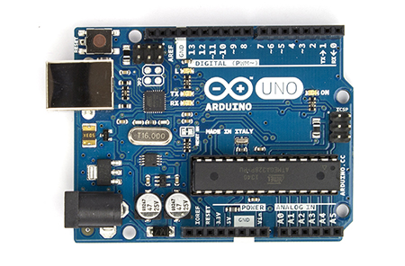
I recently got an Arduino Uno. The glut of cheap AD9850 boards on e-bay made one an obvious first purchase to complement the Arduino. I made an Arduino and AD9850 VFO which was a good learning experience but I didn't have any immediate need for a VFO.

I have been wondering about the efficiency of my HF antennas recently and I fired up WSPR
on my pc one day. Immediately I realised that an Arduino and AD9850 powered WSPR transmitter would be possible.

Of course, someone had published a similar project on the Internet. George Smart, M1GEO, has posted a project on his web pages describing an Arduino based AD9851 WSPR transmitter. However, there are some crucial differences between the two chips and I also found that George's Arduino code didn't work well with the GPS I was using.

So, my project is based heavily on M1GEO's, but with additional help and information provided by other web pages. My own contribution is largely in enhancing the Arduino code and integrating the project from various sources.

Challenge #1 - accurate timing

WSPR relies on stations starting to transmit between seconds 1 and 4 of even minutes. Consequently an accurate time source is necessary. I already had a GPS 'puck' and it is a trivial task to connect a GPS to the Arduino using the TinyGPS library. However, the Arduino is expecting a TTL level signal from the GPS and my device outputs RS-232. Hence, a converter between the two voltage levels is required. Fortunately there is a handy chip that does this called the MAX232. Connecting this between my GPS and the Arduino meant that I was able to use the TinyGPS library to receive the NMEA sentences from the GPS. If you use a GPS module like the one described in this article, you will not need the MAX232 chip.

Challenge #2 - differences between the AD9851 and AD9850

There are two main differences to be aware of. Firstly, the AD9850 has a different oscillator frequency, it uses 125Mhz whereas the AD9851 uses 180Mhz. Secondly, the AD9850 requires a different set of pins to be set HIGH to enable serial mode, ie. to be able to write data to it serially rather than in parallel. Pins RESET, CLOCK and LOAD all have to be set HIGH (pins labelled RESET, H_CLK and FU_UD respectively on my DDS module).

Challenge #3 - switching an amplifier

The output from the DDS module is very low. I am feeding this to a QRP HF amplifier which generates around 250mW. However, I needed to switch the amp on and off in line with the times when the WSPR signal was being transmitted. It is easy to set a pin on the Arduino to HIGH at the start of the transmission sequence and to use this to drive a transistor switch connected to a relay, as described here. The relay switches the power to the amp on and off.

Challenge #4 - generating more power from the HF amplifier

To be continued, my amplifiers never seem to be able to output more than a couple of hundred milliwats so I need to do some more work here.

Challenge #5 - building an effective low pass filter

A low pass filter is essential to ensure no harmonics are transmitted. I've not had much success building these either so am going to work on this next. buy an LPF kit from Hans Summers, G0UPL For £2.50 you can't really go wrong. I bought filters for 20m and 30m so at some point I will implement antenna switching as well.

Arduino Sketch

The Arduino sketch I have modified and that works for the AD9850 and my GPS can be downloaded from here. You will need to generate the WSPR tones as described in M1GEO's post here and amend the sketch with tones specific to your callsign, location and power level. If you use this version please add a line to turn off the GPS interrupts during the WSPR tx period, add 'ss.end();' between lines 141 and 142.

I have since added a 4 line by 20 character I2C LCD display. I have also fixed the timing issue that didn't seem to occur without the LCD but is caused by interrupts from the GPS delaying the internal clock thus making it useless for WSPR. The updated version can be downloaded here.

Note: you will also need to download and install a few libraries:

If you open the Arduino serial monitor when the sketch is running you will see the timing string from the GPS and when the WSPR tx is activated.

Here is a picture of my Arduino Uno, AD9850 DDS board and breadboard with the MAX232 chip and amplifier power switching circuit - ugly at the moment but it works.


Wednesday, 14 August 2013

The trials and tribulations of HF portable

Recently I bought an FT817. There were two reasons for this, firstly, to drive the 70 Mhz transverter I have built, and secondly so I could do some portable HF operating.

After paying ML&S a princely sum for a Wonder Wand antenna to go with the 817 I was underwhelmed with its performance. I will be generous and attribute this to the less than stunning take off from my QTH. However, I knew I could do better.

On trawling the Internet I came across the HF Pack website and found the page relating to their antenna shoot-out. The PAC-12 antenna designed by James, KA5DVS performed well compared to the reference vertical and James has published the design here.

It took me some time to produce my own version but I now have a reproducible design. 

The 72 inch telescopic whip from the Wonder Wand has been reassigned as the top section of my PAC-12. I have built three loading coils, for 40m, 20m and 17m. For the coils I used 16SWG enamelled copper wire. For some reason I found that I needed a lot more turns on the coils than James's design to make the antenna resonate at the appropriate frequency.


My version of the PAC-12, with coils for 40m, 20m & 17m.

My version does not need the threads cut into the rods as in James's design as for the bottom section I used a hollow rod which started life as the support for a light. That, some black tubular conduit that I found in my shed and some 15mm plastic water pipe and end-stops are the other main components.

In Clas Ohlsen I found brake pipe connectors, which I have used inserted into the water pipe end stops to mount the telescopic antenna into. Ideally these would have been about twice as long and if I find a suitable alternative I will replace them. At one end of these brake pipe connectors is a smaller hole, through which I inserted a small bolt with a solder tag and nut on the lower side to solder to the top of the loading coil, see picture below.


Through the end stop and the brake pipe connector I drilled a small hole to take a screw that is used to retain the telescopic section.

The bottom end of each coil has a solder tag type connector attached to the end of the coil and this is threaded through the bolt that goes through the top of the hollow rod that forms the bottom section of the antenna.

The hollow rod fits neatly inside the plastic conduit and I have a bolt through the conduit that the rod rests upon. The plastic conduit can then be tie wrapped to a tripod for support or just supported by a couple of large rocks.

Through the very bottom of the hollow rod I have a self-tapping screw to connect a piece of wire which is then taken out to an SO239 connector. I also have a phono socket connected to the screen of the SO239, my counterpoise wires are attached via a phono plug to the socket.

In the garden at home and on the balcony of our holiday apartment the antenna works well.

However, the connections failed the ruggedness test. On holiday in Switzerland we were surrounded by 4000m peaks. We were at 1800m so there was over 2km of towering rock for any signals to get through. As we were close to the border with Italy 40m was always full of Italian stations, in the apartment there was a lot of interference on 20m, and I heard a few station on 17m (most notably one from Bahrain running 1kW).

So it seemed like there was a need to get higher. One day we caught a cable car up to around 2700m to a point with a fantastic take of in most directions. The picture below is of the TV transmitter about 200m below the location.


So with the antenna set up I had a listen around on 20m. There was a UK station just completing a contact with a US station. However, my SWR seemed a little too high so I decided to switch to 40m. I immediately heard a portable DL station calling CQ SOTA. He was very strong. However, I had a noise figure of S0 rather than the more normal S7 so I was suspicious. A quick whistle into the microphone confirmed that my SWR was very high. Further investigation showed a small design flaw in the connection of the hollow rod to the SO239 that I could not resolve. During a quick tune round I heard an French portable station also calling CQ SOTA.

I'm sure I could have made a few contacts but I need to make some alterations so that the antenna passes the ruggedness test. When I have made these alterations I am looking forwards to taking the antenna out portable away from home. We live in a bit of a hole in the ground and I am intrigued what HF reception I will get on one of the high points in Surrey.